A linkage walker is a linkage that at the very least tries to mimmic the motions of a leg
These are the four most important parts
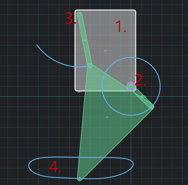
1. The ground, in the case of walkers this is the body the linkage is attached to.
2. In this case this is the crank. In other linkages there can be more than one (we will get to that) or it could be something like a piston instead of a rotating servo.
3. Unpowered joints. These are important because it is what gives the linkage its unique footpath or motion.
4. Footpath. This is the path the tip of the linkage takes, and is meant to be the contact path of the linkage to the ground. How this path looks can mean very different walking results.
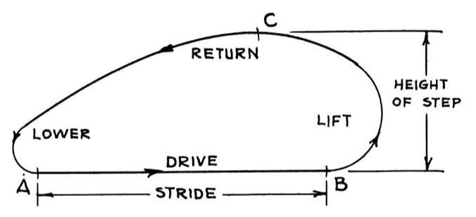
Here is also the names of the footpath parts I will be using
The software I am going to be using is called "MotionGen", and can be accessed here:https://motiongen.io/
To use MotionGen, you can start by drawing some links using the "draw link" tool from the menu to the right. They have to be connected, and have to be three (we are making a three bar linkage for now). To add a crank you can click on a joint and a menu will appear. Before you can add a "servo" you will need to add the ground.

1. Add the ground
2. Add rotational actuator (aka servo)
There are other options but those are not yet important
Drag the other point that is on the ground to the point on the other side of the linkage (make sure you have the cursor tool selected), so it will look something like this:
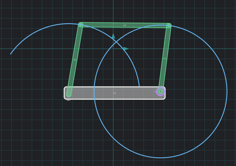
Now it might not be identical, but that's not an issue as it will still be a 4 bar linkage. The important thing here is that the program generated some motion paths for our links.
If your crank isn't displaying a full circle, that means the linkage wouldn't work at a full rotation. It looks something like this when it hits its angle limits
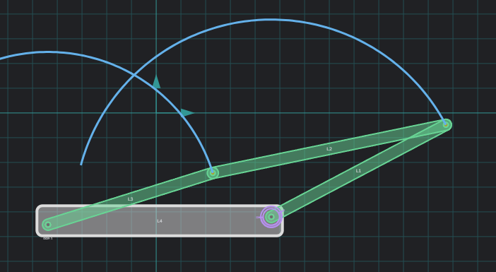
These are the problems you will need to watch out for, but if you move around the joints on your own you can get a pretty intuitive understanding on how they work.
Now as you might have noticed, this is not a leg :), but just a linkage, so how do we make it into a leg? As you probably already remeber there is an extra joint in the first image of this page. So yes, we will be adding that point/link. To do that, simply select this tool, and click on the middle bar of our linkage.

Now you can simply move all the points and explore all of the simple four bar links there are to create

Your goal now is to try and create as flat of a stride as possible (while ideally keeping stepping height as high as possible for rough terrain)
You can also see how your linkage moves by pressing the play button. Something to note however, is that if your linkage moves really fast on the stride, it's better to just design something new. If you used that linkage anyway it would only be good for running, or if you had a lot of legs (will get to that too)
I will be using the first linkage as an example in this section, to use some other linkage they obviously have to be aligned with the grid. MotionGen automatically has snapping to the grid enabled so that is pretty simple Getting your linkage into a game is very easy actually, simply put sevros where the joints are in a 2d plane like this

Then you can connect them. Please be mindful of collisions, for most four bar linkages this is not really a problem, but it's worth to keep in mind.
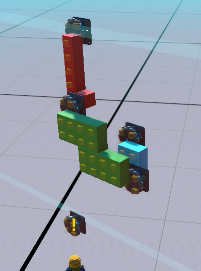
The foot joint is special, because it needs to be most of the time aligend with that lower servo (this is so the footpath is identical to the one in MotionGen). To achieve that you can for the most part use a wedge like this
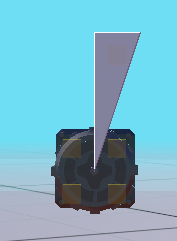
Once you have the wedge you can delete the servo as it's not needed. Then connect the wedge to the bar it originally was connected to. Now you have a completed leg.
After that it's best to create the body of the walker, or the ground as I have been calling it. Make sure to connect all "ground servos" to each other. Now you can mirror the legs over and maybe add another pair if that is what you want
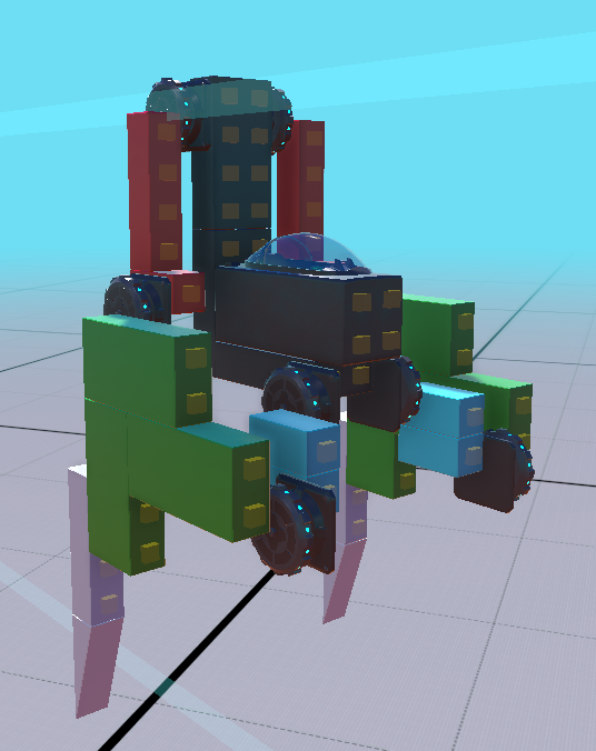
You can use gyros to keep it upright. Depending on how many legs, and how you built it, that might not be necessary.
The first thing we should do is make all of the non-powered joints "loose joints" by setting the strength to 0, but also the angle to infinity. Set the angle to infinity on all joints to ensure it moves as intended. The powered joints can have an input, ususally W and S. Enable hold postition, to ensure the legs stay synced later
Half of the servos needs to have negative speed (one side, the one moving backwards)

If you try to walk you will notice that both legs move at the same "phase" and that means the build just sways back and fourth or jumps. To fix this we can use an offset. Put an offset on every alternating leg, like this
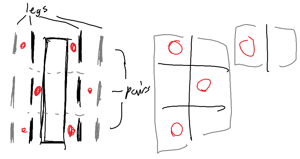
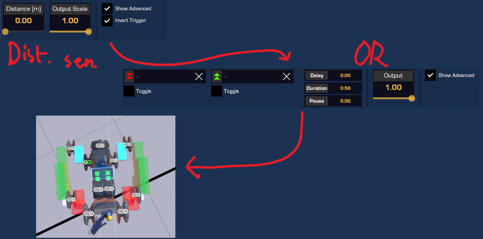
To set that offset we can use an always on (usually a zero distance distane sensor with invert trigger on) connected to any gate, ususally OR, with a 1/n*0.55 (or 0.555) duration (that is, if the crank speed is 1, it is equal to 1/1*0.55 which is 0.55, and if it is 2 it is equal to 1/2*0.55, which is 0.275)
Here is my configuration for this build, using 0.55 since it is 1 strength
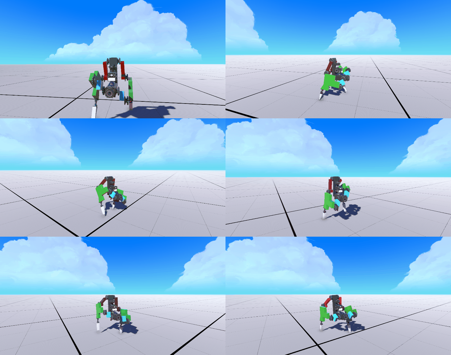
If we add suspension and test drive the walker it should walk just fine
This has been the basics tutorial.
